|

Dip. di Ingegneria
Informazione
Università
di Roma Sapienza

Fondazione Ugo Bordoni
|
Laboratory of
Radio Meteorology
Staff: F. S. Marzano, N. Pierdicca, M. Biscarini
Co-staff: F. Consalvi (FUB)
Collaborators: M. Montopoli, E. Picciotti
Laboratory of Antennas, Radiopropagation and Telesensing (LabART)
Dept. of Information Engineering - Sapienza
University of Rome
Location: Latitude 41° 53’ 37 N, Longitude
12° 29’ 38 E
Tel. +39.06.44585847; Contatti: frank.marzano@uniroma1.it
https://cispio.diet.uniroma1.it/marzano/LabRadioMet.htm
Points of view about Atmospheric Engineering Research
|
|
Lab. RadioMet OBJECTIVES
The
Laboratory of Radio Meteorology is a joint initiative of DIE and CETEMPS to
exploit ground-based remote sensing of the atmosphere in synergy with satellite meteorology. Its first
activity dates back to 1980 (thanks to an initiave
of Prof. d'Auria and his colleagues) and is a
measurements facility of the Laboratory of
Antennas, Remote Sensing and Propagation of DIE. 
The
LabRadioMet has the following objectives:
1. to manage
ground-based remote sensing and in situ instrumentation;
2. to design and
develop new microwave remote sensing instrumentation;
3. to develop
advanced algorithms for atmopheric parameter
retrieval;
4. to exploit sensor
synergy within the atmospheric observation;
5. to operate as a
ground-based facility for satellite product validation;
6. to pursue the use
of remote sensing for telecommunication applications.
This
experimental activity is carried out in close coordination with the:
|
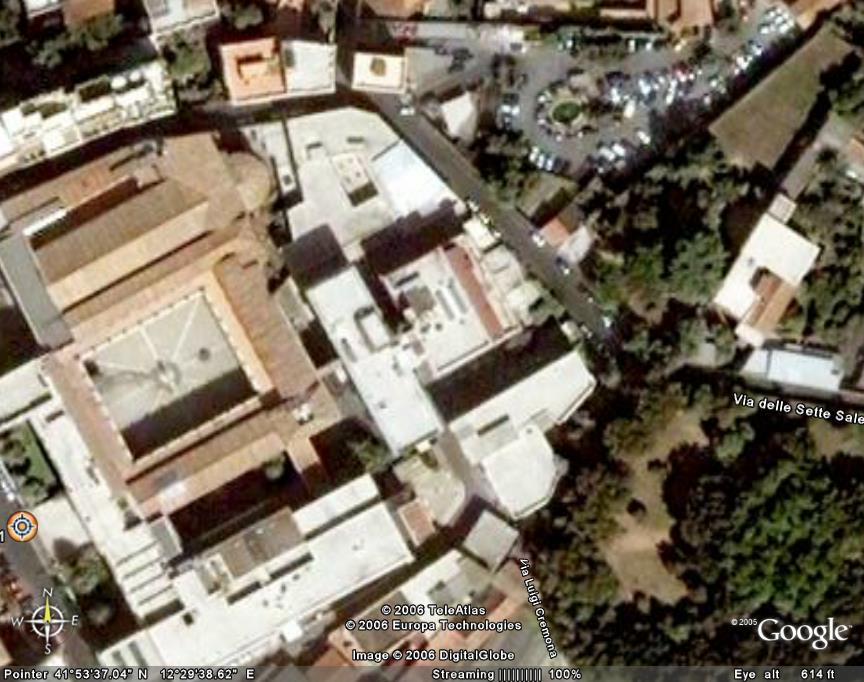
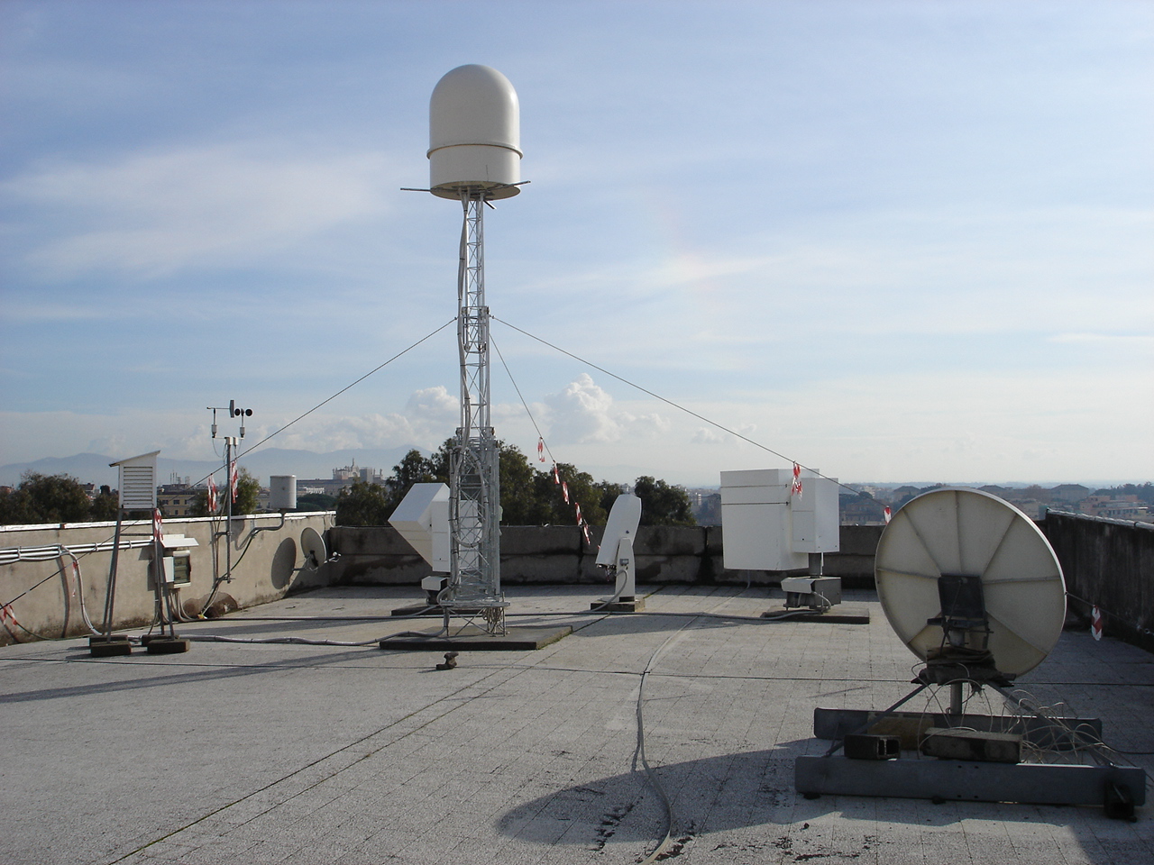
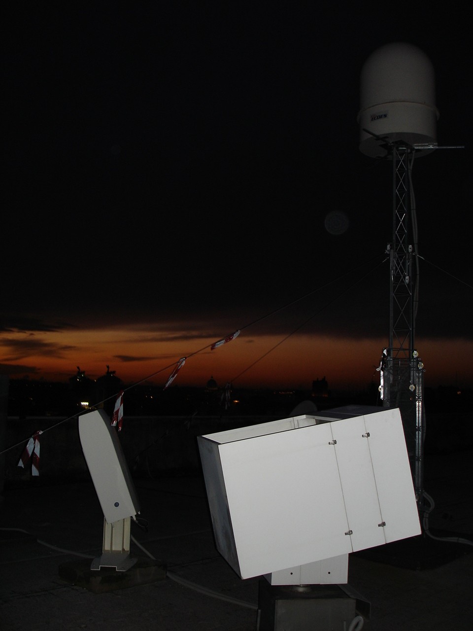
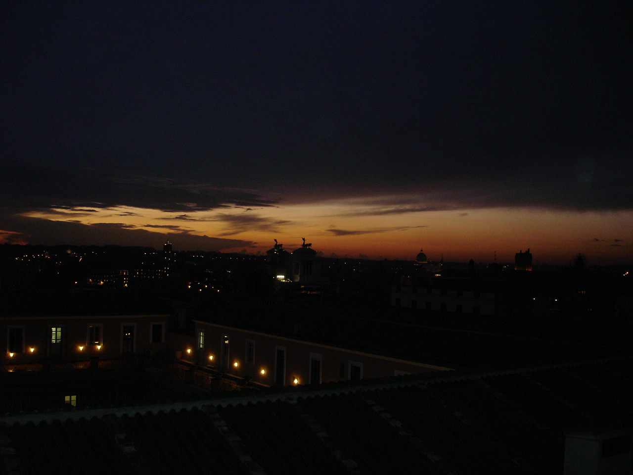
LabRadioMet views

|
Lab. RadioMet FACILITY
The
Laboratory of Radio Meteorology is placed on the roof terrace of the
Faculty of Engineering of the Sapienza University
of Rome. The test site is exactly located at: Latitude 41° 53’ 37 N, Longitude 12° 29’ 38 E.
The
position of the
Laboratory is amazing as it is on the top of the highest historical hills
of Rome, Colle Fagutal.
The view of the old city of Rome is unique, but also the optical visibility is very
attractive both towards the Tyrrenian sea and the
Appenine range.
The LabRadioMet enumerates both in situ meteorological instrumentation coupled with
microwave and optical sensors.
|
View of the LabRadioMet
measurement terrace
|
Weather
stations
Two
weather stations, spatially
separated by 15 m, are present capable to measure: pressure (hPa), temperature (K), relative humidity (%), and wind
velocity (m/s). Three tipping-bicket
rain gauges, spatially
separated to each other by 15 m, are also avalaible
capable to measure the accumulated rain (mm).
Data
are acquired every 10 minute through a RS232 line and digitally archived on
a PC system. The meteo stations are operated
separately with a redudancy principle.
|
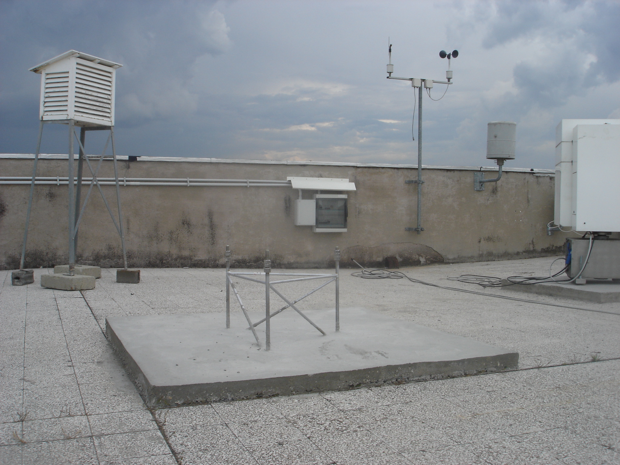
Weather stations
|
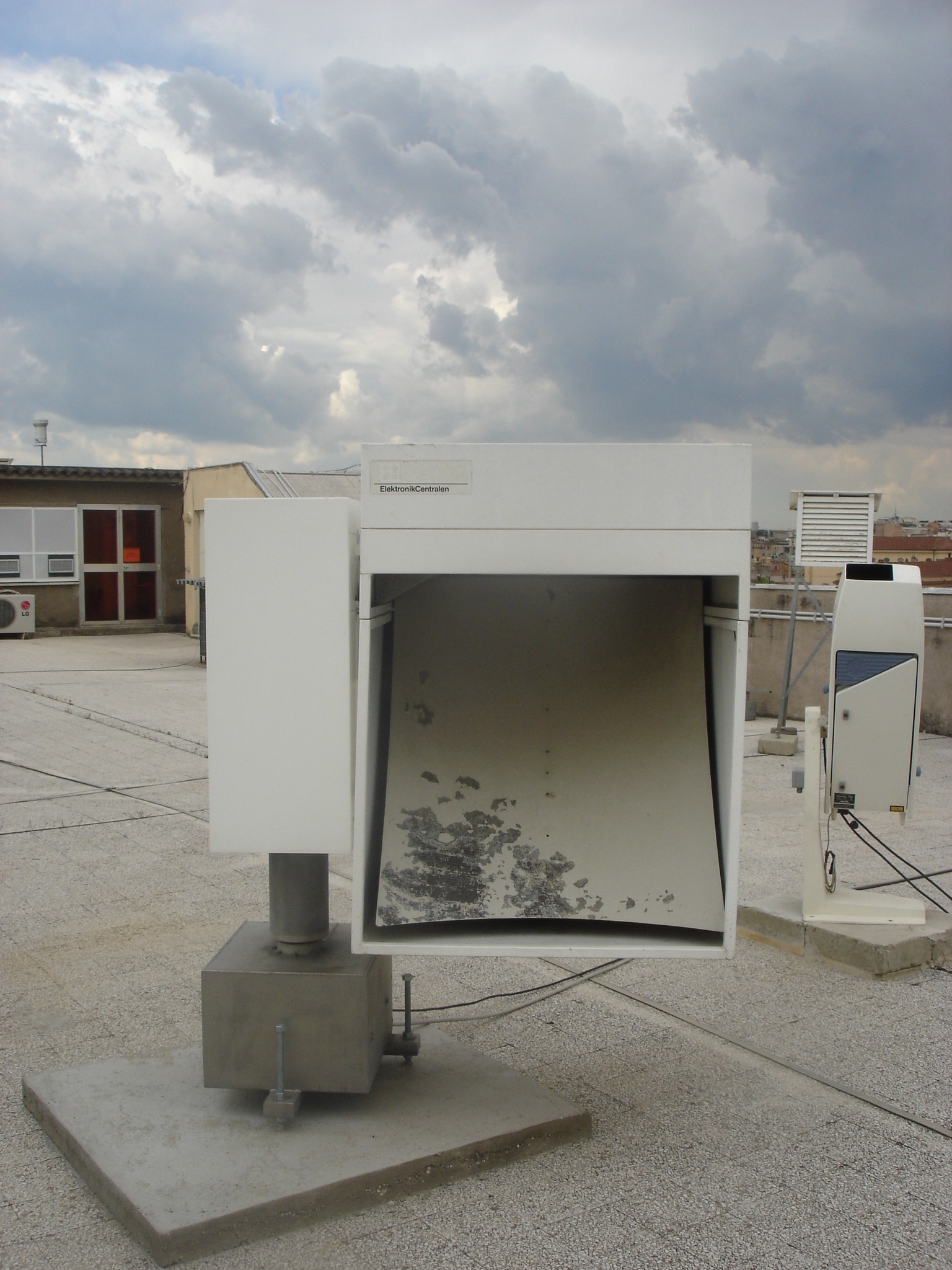
Ka-band
Microwave Radiometer
The
REC-2 radiometer is a dual channel system at 23.8 and 31.7 GHz, manufactured by
the RESCOM company (Aalorg, Denmark). This
radiometer is a compact self-contained configuration designed for automatic
unattended operation for extended time with a high measuring accuracy.
The
radiometer has an elevation and azimuth control and are controlled by a
personal computer through an RS-232 serial line. Regular calibration are
performed by using the tipping-curve method. The REC-2 radiometer consists
of offset-fed antenna parabolic reflectors connected to microwave receivers
of the noise balancing type. The noise-balancing type receiver yields a
high insensitivity to gain variations and mismatches within the noise
injection feedback loop thus ensuring a high long-term stability. The actual
temperatures of main microwave components in the front ends and feed
assembly are monitored and used for correction of measured data. The
antenna reflector and receiver sections are integrated in an outdoor box.
The
shape of the antenna surfaces and the configuration of the wide-band feed
horns have been designed so that energy outside the main lobes is
minimized. Moreover, the extremely low side-lobes can ensure a minimum
pick-up of radiation emitted from surrounding surface. By a proper design
of the feed horn, nearly equal antenna main-lobes at 20 and 30 GHz have
been obtained. The REC-2 corrugated feed horns is protected by an aperture
window and is connected to a diplexer by a short waveguide bend. The REC-2
circular horns are horizontally polarized and placed above the antenna
reflectors downward so that to be protected against rain drops, snow and
condensation layer. The REC-2 antenna reflectors are of carbon-fiber
skin-honeycomb construction. They have a very smooth surface with roughness
less than 0.2 mm. Their rectangular contour provides a projected aperture
of about 60 x 60 cm^2 for REC-2. Heated air is continuously blown across
the antenna reflector which presents a set of small holes within its vertex
area, thus preventing the formation of the dew and the possible
accumulation of rain drops, snow and hail on the surface. Moreover, air
from heater box is directed through a tube to the feed horn window. In this
way the window will be kept free from condensation or rain drops.
|
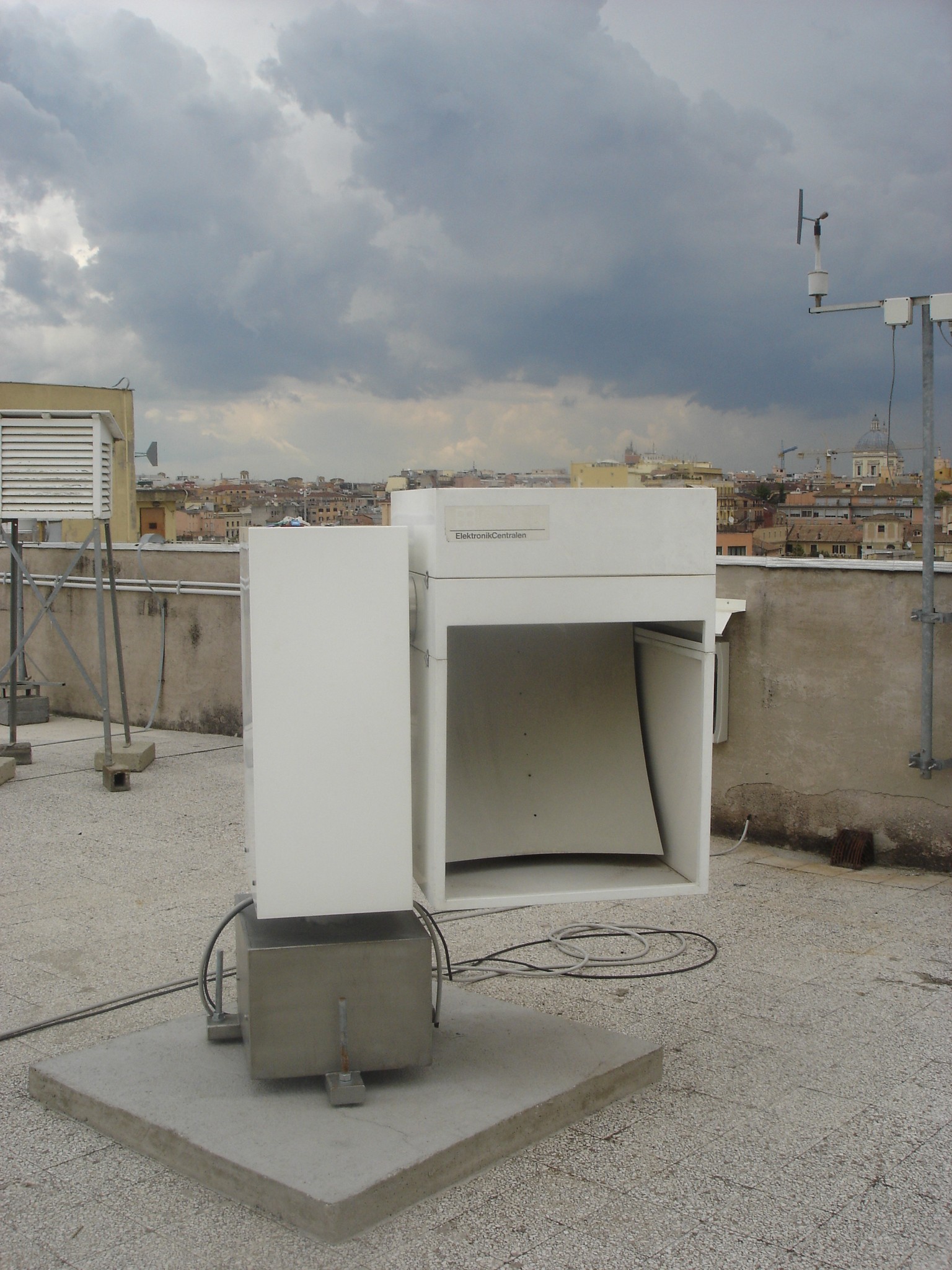
Ka-band microwave radiometer
|
|
Ku-band Microwave
Radiometer
The REC-1 single channel radiometer
is an independent system, designed also by the RESCOM. The operating
frequency is 13.0 GHz and, basically, it has almost the same
mechanical characteristics of REC-2.
The
radiometer has an elevation and azimuth control and are controlled by a
personal computer through an RS-232 serial line. Regular calibration are
performed by using the tipping-curve method. The REC-1 radiometer consists
of offset-fed antenna parabolic reflectors connected to microwave receivers
of the noise balancing type. The noise-balancing type receiver yields a
high insensitivity to gain variations and mismatches within the noise
injection feedback loop thus ensuring a high long-term stability. The
actual temperatures of main microwave components in the front ends and feed
assembly are monitored and used for correction of measured data. The
antenna reflector and receiver sections are integrated in an outdoor box.
The
shape of the antenna surfaces and the configuration of the wide-band feed
horns have been designed so that energy outside the main lobes is
minimized. Moreover, the extremely low side-lobes can ensure a minimum
pick-up of radiation emitted from surrounding surface. By a proper design
of the feed horn, nearly equal antenna main-lobes at 20 and 30 GHz have
been obtained. The REC-1 corrugated feed horns is protected by an aperture
window and is connected to a diplexer by a short waveguide bend. The REC-1
circular horns are horizontally polarized and placed above the antenna
reflectors downward so that to be protected against rain drops, snow and
condensation layer. The REC-1 antenna reflectors are of carbon-fiber
skin-honeycomb construction. They have a very smooth surface with roughness
less than 0.2 mm. Their rectangular contour provides a projected aperture
of about 90 x 90 cm^2 for REC-1. Heated air is continuously blown across
the antenna reflector which presents a set of small holes within its vertex
area, thus preventing the formation of the dew and the possible
accumulation of rain drops, snow and hail on the surface. Moreover, air
from heater box is directed through a tube to the feed horn window. In this
way the window will be kept free from condensation or rain drops.
|
Ku-band microwave radiometer
|
|
X-band Meteorological
Radar
The X-band Meteorological radar,
designed by ELDES (Firenze, Italy), is a compact portable scanning radar
with the following features: peak power of 10 kW, selectable pulse
repetition frequency (PRF) between 800 Hz (maximum range of 180 km), pulse
duration of 0.6 ms
(range resolution of 90 m) and an antenna directivity of 39.1 dB (about 3°
half-power beamwidth). The radar control and data
acquisition is completely remote and accessible via Internet connection.
The
X-band radar has a low-noise receiver with a noise figure of about 4 dB, a
coaxial magnetron transmitter, a parabolic reflector of about 90 cm
diameter with a corrugated rectangular horn feeder, and a digital recever sampling the received signal at the
intermediate frequency of 40 MHz. The minimum detectable
power signal is about -113 dBm, whereas up to 128
samples may automatically integrated. The azimuth scanning is complete with
an angular resolution between 1° and 3°, while the zenith scan ranges from
0° to 180°. The entire receiving and transmitting system is mounted on the
backside of the reflector and rotates with the antenna itself, protected by
a single-component radome. The total weith of the X-band system is about 75 kg and can be
easily removed and installed.
|
X-band meteo radar
|
|
Near-infrared Mini Lidar
The Vaisala
CT25K is a field-proven and popular laser ceilometer
for measuring cloud height and vertical visibility at near infrared. It
employs pulsed diode laser Light Detection and Ranging (LIDAR) technology
at 904 nm to detect clouds, precipitation and other obstructions to vision.
The
CT25K's unique single-lens design ensures excellent performance at low
altitudes, which really counts for aviation safety. Starting at a height of
virtually 0, the Vaisala CT25K Laser Ceilometer measures cloud height - or vertical
visibility if the cloud base is obscured - with unmatched accuracy. The
single-lens design also ensures reliable measurement in fog, rain, snow and
haze. No field adjustments are needed. The CT25K can be tilted on its pedestal
base, allowing the beam to be directed manually in any direction between
-15...+90º from the vertical. Tilting improves the protection given by the
shield to the window, and makes it easy to perform field testing against a
hard target. In the measurement unit, a tilt angle sensor automatically
corrects the cloud distance reading to the vertical cloud height. The CT25K
is fully automatic. It transmits messages containing cloud height and
instrument status information to a controller, display unit or central
computer. Its software includes an extensive set of self-diagnostic
routines to ensure reliable operation and easy trouble-shooting. The CT25K
also has a modular structure and easy-access door to ensure fast servicing
and high data availability. Vaisala's Sky
Condition Algorithm is provided as an option. This algorithm calculates the
cloud amounts and the heights of different cloud layers, in order to
construct an approximation of the entire sky. Vaisala
CT-VIEW software can be used to view backscatter profiles, cloud detection
and backscatter density graphs, and to perform data logging and storage
functions in the Windows PC environment. The CT25K can be used stand-alone
or as an integrated sensor in a weather observation system comprising many
sensors, displays and central computers.
|
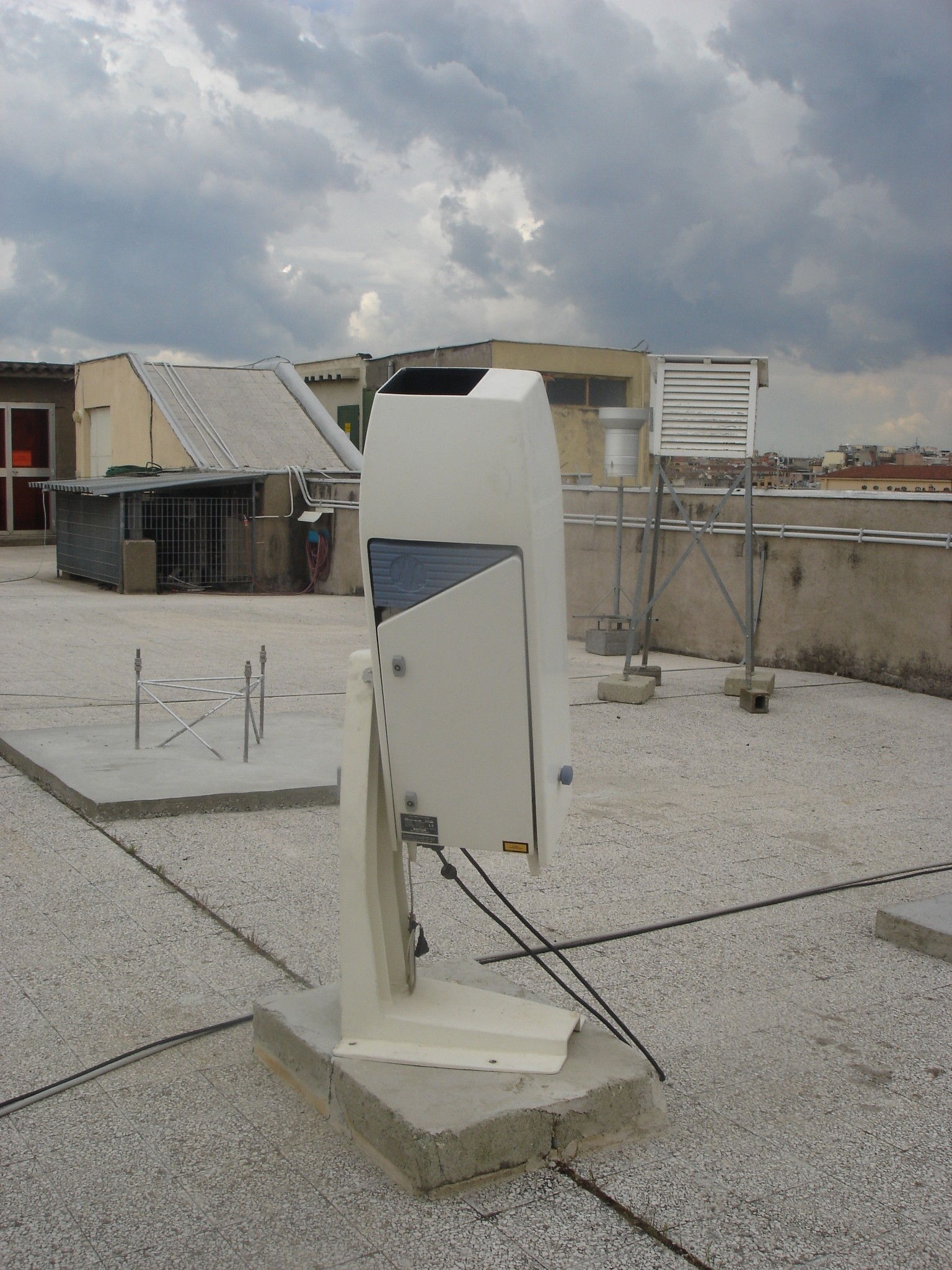
Near-infrared mini lidar
|
|
W-band Microwave
Radiometer
The W-band single-channel polarimetric radiometer is an independent system,
designed by DIET. The operating frequency is 90.0 GHz at both
horizontal and vertical polarization. It is an indoor installation with an
outdoor motorized oscillating reflector.
The
W-band radiometer consists of a dual corrugated rectangular horns connected
to microwave receivers of the Hach type with two
microwave loads. The actual temperatures of main microwave components in
the front ends and feed assembly are monitored and used for correction of
measured data. The antenna and receiver sections are integrated and a
regular calibration are performed by using the tipping-curve method and the
criogenic loads.
|
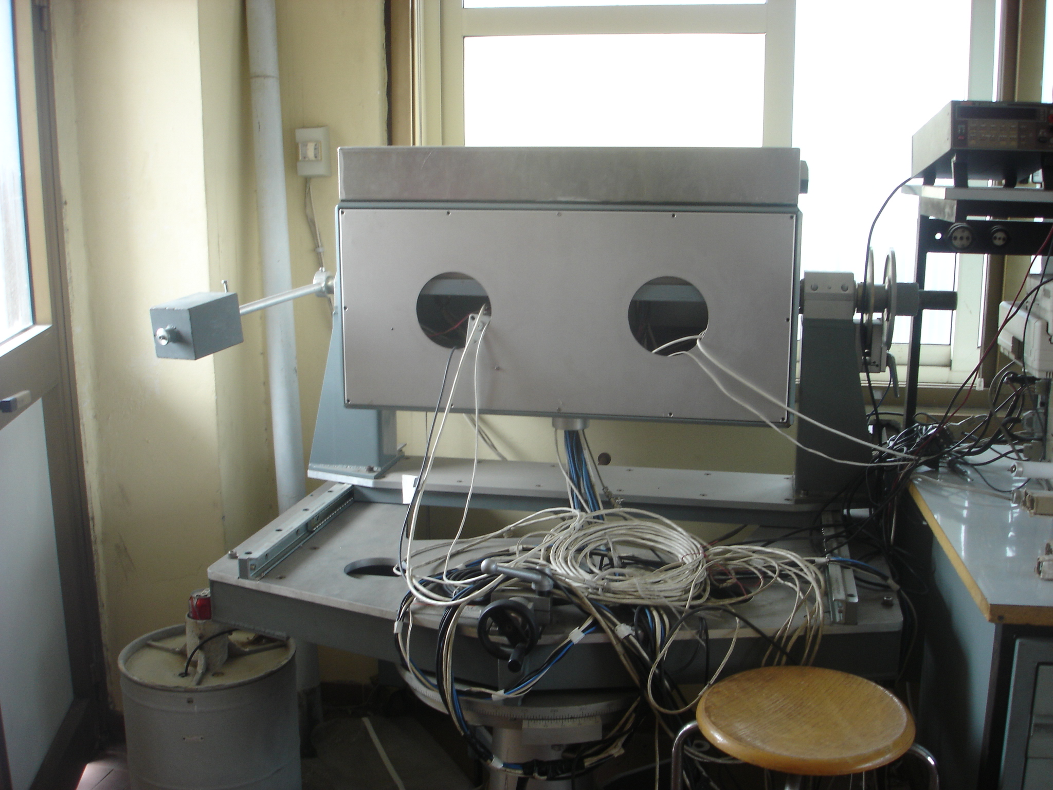
W-band microwave radiometer
|
|
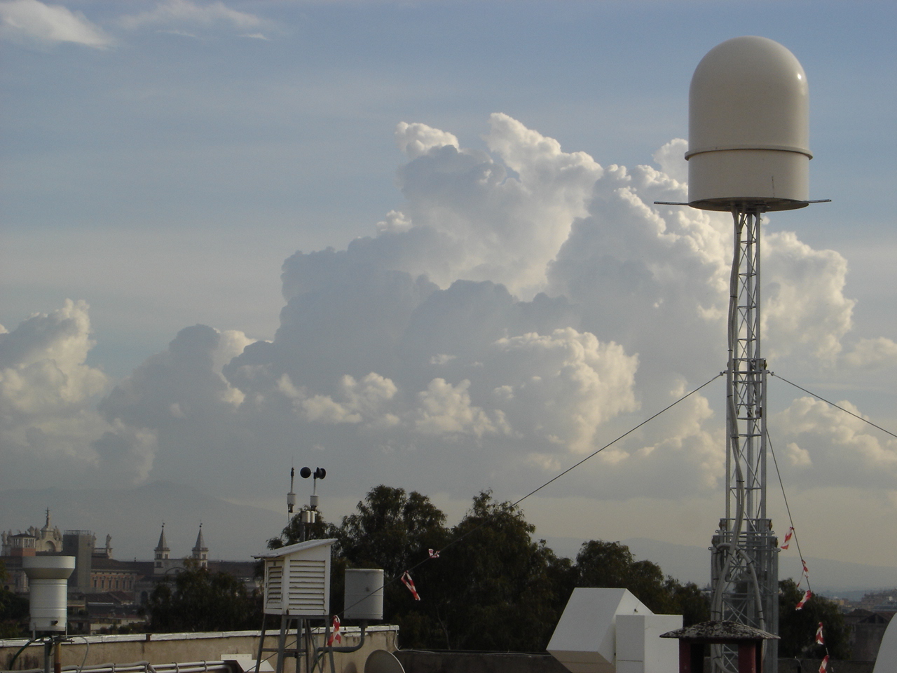
Ka and Q band
Satellite Receiving Station
A Ka-band and Q-band satellite
receiver station is also present on the roof terrace. It was previously
used for Olympus satellite signal reception and is now at disposal of the research
group for AlphaSat TD5 Aldo experiment.
The
Ku band system is made by a parabolic reflector of 2 m diameter with a
corrugated horn feeder. An LNA block provides the outputs signal at
intermediate frequency. At Ku the station has also the capability to trasmit. The Ka band feeder is interachangeable
with the Ku-band one.
|
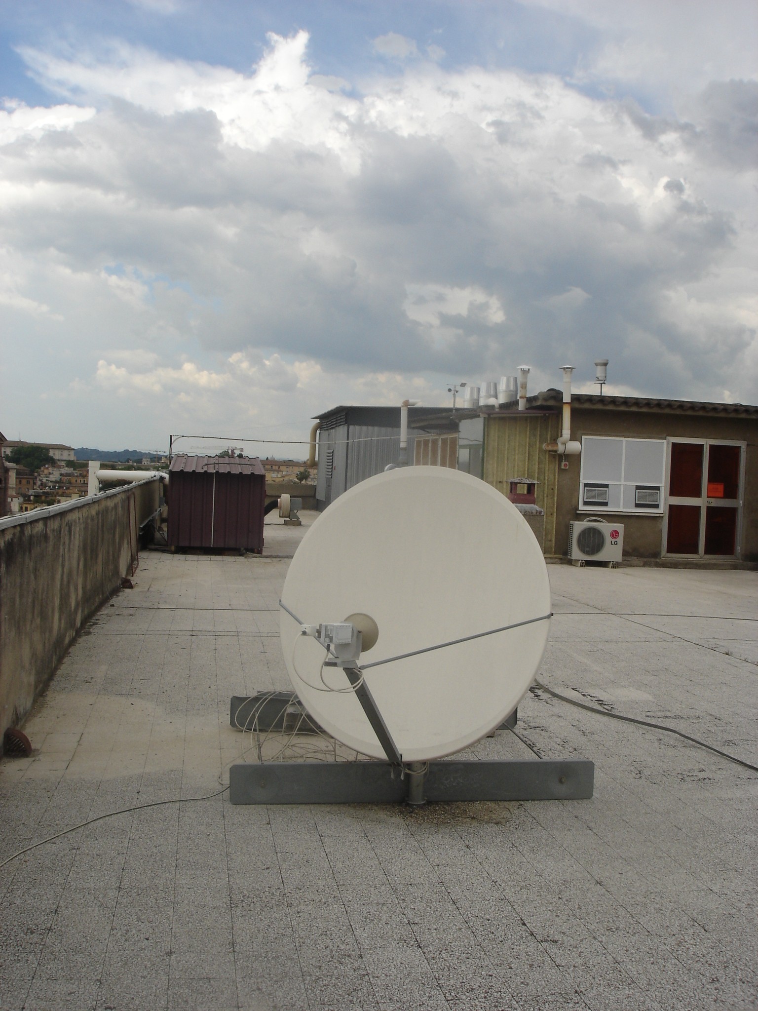
Ku- and Ka-band satellite receiving station
|
|
VLF Lightning Sensor
A
VLF receiver has been installed in May 2011. The receiver is part of
the internation BlitzOrtung lightning network (www.blitzortung.org) and
contributes to the voluntary cloud-to-ground lightning measurement
database and geolocation processor, managed in Dusseldorf (De).
The VLF (3-30 kHz) sensor is made by two orthogonal ferrite loop antennas,
a pre-amplifier, a GPS receiver and a PC traker program, connect via
LAN to the central database. The VLF band is chosen due to the peak of
radio-emission generated by cloud-to-ground lightnings. The
receiving antenna is placed within a meteorological box to prevent from
rainfall (close to a raingauge, see aside), whereas the GPS and the
processor borad are located inside the laboratory at a distance of
about 10 m.
|
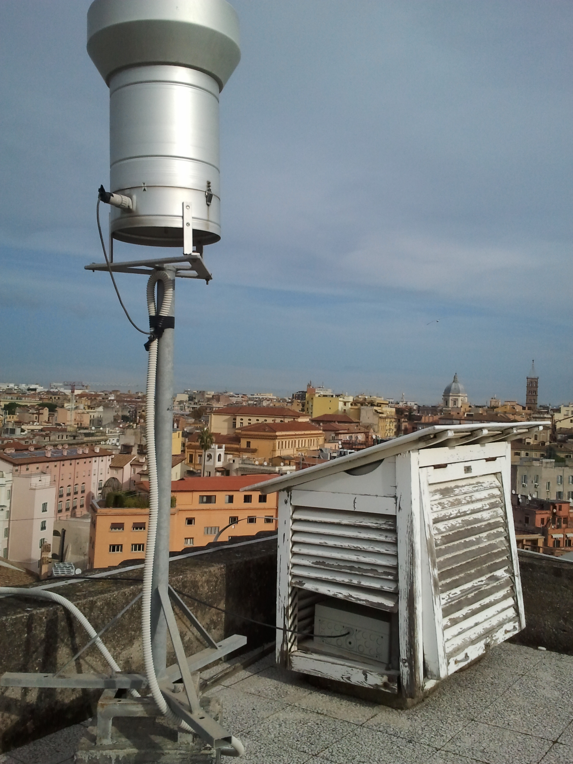
VLF lightning sensor
|
|
Precipitation Optical Disdrometer
A
precipitation optical disdrometer has been installed in November 2011,
thanks to the international MarieCurie project HYDREX. The Parsivel
disdrometer is produced by OTT and is able to provide the size
distribution of precipitation particles and their category (rain, snow,
grupel and sub-species).
The Parisevl optical disdrometer by OTT works on the principle
to measure the effects of precipitation particles on the optical
near-infrared beam transmitted and received within a length of about 40
cm. From the beam attenuation the particle concentration is basically
estimated, whereas the size, their distribution and species is dereived
from the velocity measurements within the measurement area couple with
amplitude perturbation.
|
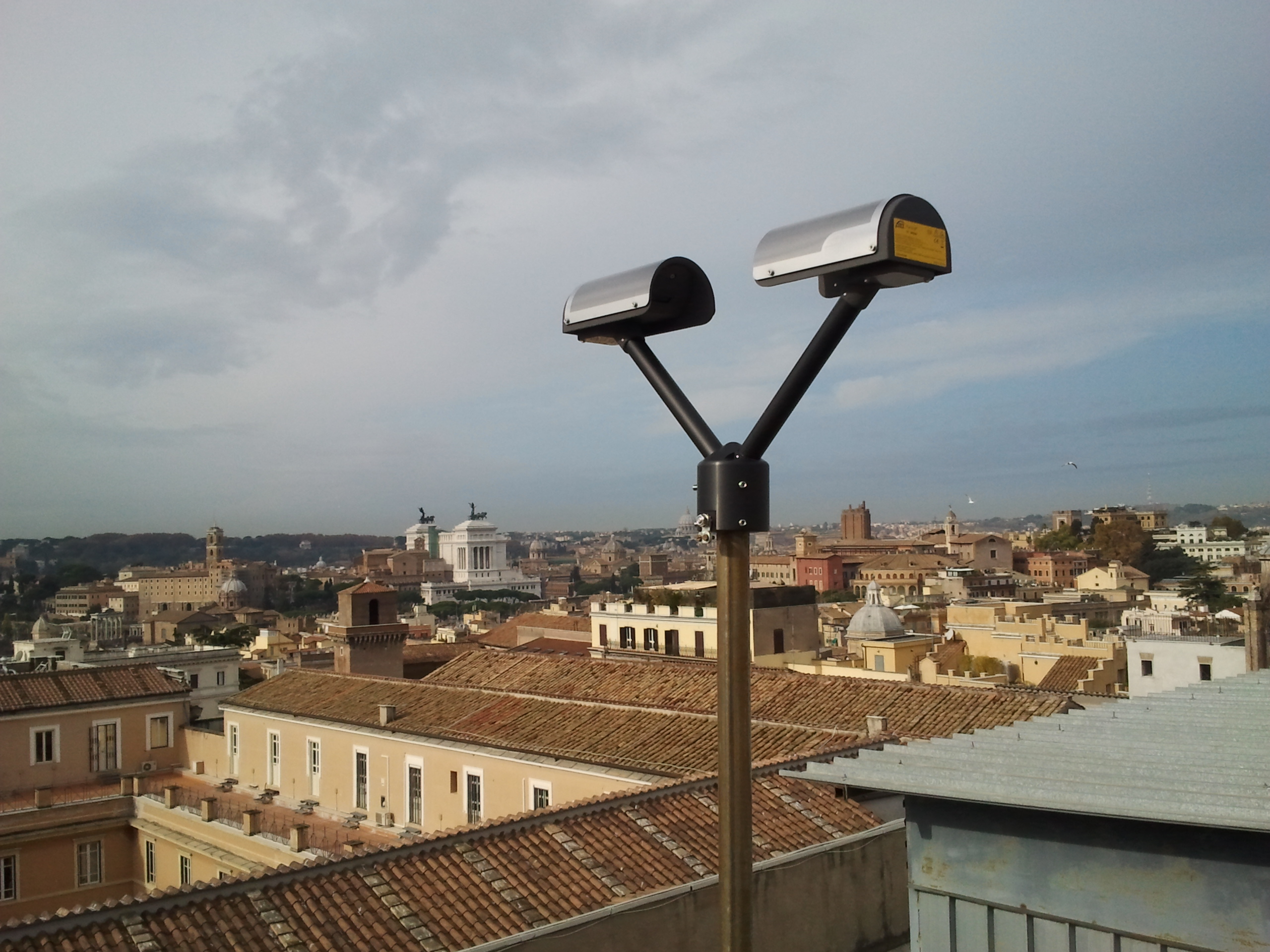
Precipitation optical disdrometer
|
Lab. RadioMet
RESEARCH
The
Laboratory of Radio Meteorology current research concerns passive and active remote sensing of the atmosphere from ground-based, airborne, and space-borne
platforms, with a particular focus on clouds and precipitation using
microwave and infrared data, development of inversion methods, and radiative transfer modelling
of absorbing and scattering media
Other
main topics of interest are radar meteorology for rain, wind and ash retrieval and synthetic
aperture radar data processing for land-use applications.
The
LabRadioMet is also deeply involved in radiopropagation
studies, including e.m. field scintillation and
rain fading modelling and data analysis along
satellite microwave and millimeter-wave links.
Joint researches are carried out together with national
institutions (e.g., CETEMPS - Univ. of L'Aquila, CIMA - Univ. of Genoa,
ARPA-SIM - Bologna, CNR ISAC - Roma, DPC - Roma), international
institutions (e.g., NRL - CA USA, Univ. of Washington - WA USA, Colorado
State Univ. - CO USA, ECMWF - Reading UK) and industries (e.g., Selex Gematronik -
Germany/Italy, ELDES - Italy, Telespazio - Italy,
Datamat - Italy).
Within the LabRadioMet
tasks, there are also educational purposes. About 30 undergraduatestudents, more than 20 graduate students
and 6 Ph.D. students have been working on the topics of interest of the
Laboratory.
The LabRadioMet
is connected to the Doctorate in Electromagnetics
of the University “La Sapienza” of Rome, to the Doctorate
in Methodologies and Technologies for Environmenal
monitoring of the University of Basilicata, and to the the
International Summer School on Atmospheric and Oceanic Sciences
(ISSAOS) of L’Aquila.
|
Research topics
and examples
Electromagnetic theory
|

|
Radiative transfer models through the atmosphere at microwaves (e.g.,  ) )
|
|
|
Scattering and absoprtion
of e.m. radiation from particle dispersion
(e.g., )
|
Electromagnetic propagation
|
|
Signal scintillation at microwaves and
millimeter-waves due to turbulence (e.g., )
|
|
|
Radiopropagation via satellite at microwaves and
millimeter-waves (e.g., )
|
Atmospheric remote sensing
|
|
Methodologies of inversion of remote sensing
measurements (e.g., )
|
|
|
Microwave and infrared radiometry of the Earth
atmosphere and surface (e.g., , )
|
|
|
Radar meteorology and rainfall retrieval at
microwaves (e.g., )
|
|
Back
|